I did a review of the cold dust in galaxies from nearby to high-redshift (mostly observational results) last semester in the group activity. I think it’s good for me to post the slides here and to share with you. However, I may have made a lot of mistakes, and I’d like to discuss them with you.
Tag: Submm
Estimating the integration time of SCUBA-2
IF a source location is known and then we need NEFD (Noise Equivalent Flux Density: the level of flux density required to be equivalent to the noise present in the system, from Wikipedia), namely the sensitivity of the instrument, to estimate the integration time needed to do the observation. Usually, the NEFD can be expressed as the flux density per square root of integration time, ![]() . For a single bolometer, we can express the relation as below,
. For a single bolometer, we can express the relation as below,
(1) ![]()
and the ![]() is the exposure time of the bolometer while
is the exposure time of the bolometer while ![]() is the RMS of the map.
is the RMS of the map.
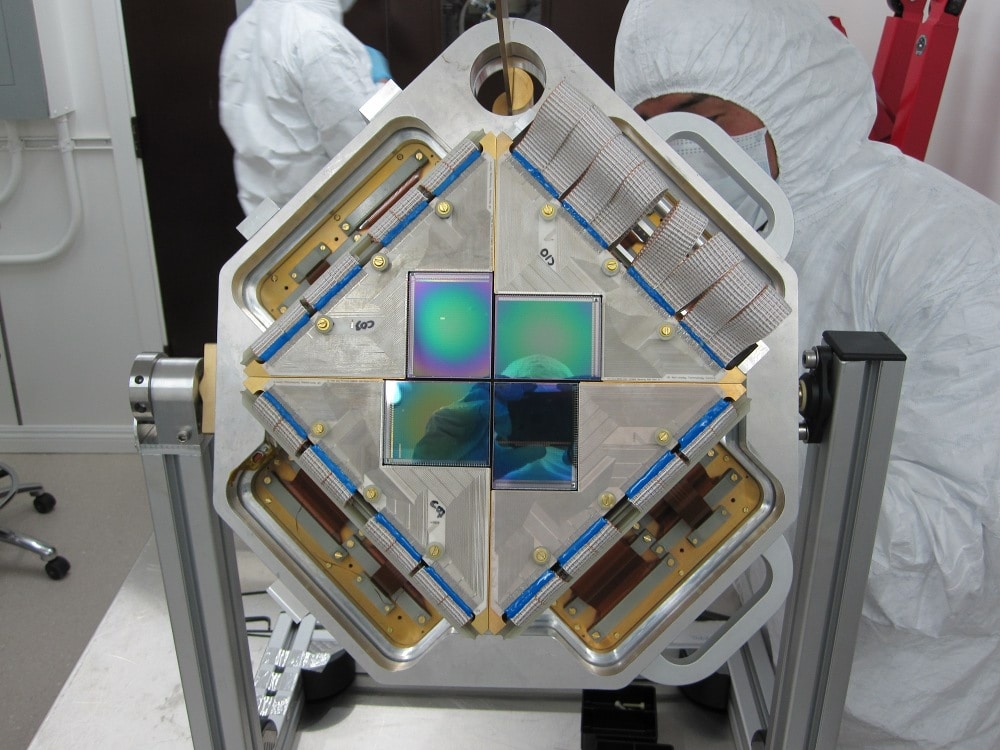
Let’s consider the SCUBA-2. SCUBA-2 is a TES-based submillimetre camera who has 10,000 pixels mounted on the JCMT(James Clerk Maxwell Telescope). It has a 7×7 arcmin FoV at both 450![]() and 850
and 850 ![]() . So, in fact, SCUBA-2 is made of 10,000 pixels, and this will make some difference to the Eq.(1). Also, we must consider the practical observation is not just simply mapping the object still. It will use some pattern to be sure of the full sampling. For SCUBA-2, they design mainly two kinds of mapping mode. One is for the small and compact sources (mainly stars or planets in the Galaxy or some extragalactic objects) of order 3′ or less. This mode is called CV Daisy. Another pattern is called PONG patterns, whose shape is close to a rectangle. SCUBA-2 uses three kinds of PONG patterns for mapping larger fields, mainly Galactic regions or very nearby galaxies. Those patterns contain three sizes: 900″×900″, 1800″×1800″ and 3600″×3600″, and each of them has 11, 5 and 8 rotations of the field respectively. So we must consider how the telescope mapping the field when calculating the exposure time from the observation time (Elapsed Time). However the formula is complicated (you need to consider a lot of things as patterns, beam size and the size of the objects, etc), but SCUBA-2 12A Call for Proposals Page gives the formula in a simple way:
. So, in fact, SCUBA-2 is made of 10,000 pixels, and this will make some difference to the Eq.(1). Also, we must consider the practical observation is not just simply mapping the object still. It will use some pattern to be sure of the full sampling. For SCUBA-2, they design mainly two kinds of mapping mode. One is for the small and compact sources (mainly stars or planets in the Galaxy or some extragalactic objects) of order 3′ or less. This mode is called CV Daisy. Another pattern is called PONG patterns, whose shape is close to a rectangle. SCUBA-2 uses three kinds of PONG patterns for mapping larger fields, mainly Galactic regions or very nearby galaxies. Those patterns contain three sizes: 900″×900″, 1800″×1800″ and 3600″×3600″, and each of them has 11, 5 and 8 rotations of the field respectively. So we must consider how the telescope mapping the field when calculating the exposure time from the observation time (Elapsed Time). However the formula is complicated (you need to consider a lot of things as patterns, beam size and the size of the objects, etc), but SCUBA-2 12A Call for Proposals Page gives the formula in a simple way:
Those formulae represent the observation time in a given transmission (which contains the declination and ![]() ) and the
) and the ![]() (in Jy/beam) you want to achieve. For example, if I want to know how long I should take to make a
(in Jy/beam) you want to achieve. For example, if I want to know how long I should take to make a ![]() detection of Stephan’s Quintet at
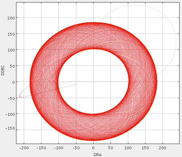
detection of Stephan’s Quintet at ![]() . Firstly, I need to know the size of the object and choose the right pattern, which turns out to be Daisy pattern as below.
. Firstly, I need to know the size of the object and choose the right pattern, which turns out to be Daisy pattern as below.

A “CV Daisy pattern”. The telescope executes a pseudo-circular pattern which keeps the target coordinate on the array throughout the integration. from: SCUBA-2 Support Information
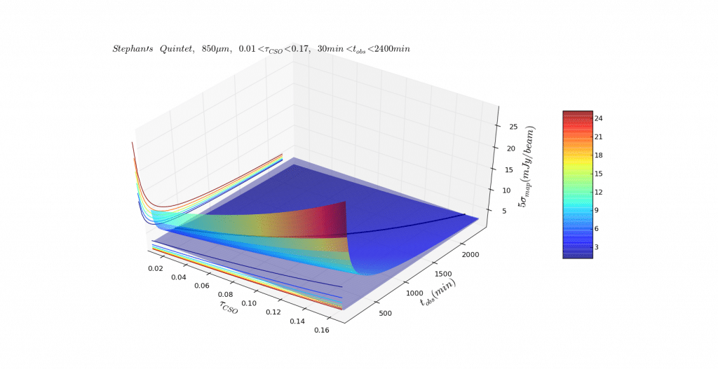
Secondly, I need to estimate the flux density from Hcg 92, which is 3 Jy/beam for a guess. Then I did a plot of ![]() ,
, ![]() and
and ![]() with the Hcg 92 flux plane across the surface, using a black line to show the intersection between to surface.
with the Hcg 92 flux plane across the surface, using a black line to show the intersection between to surface.
And the black line can be used to estimate the time you should use to observe the object. But in fact, I think this surface is just a beautiful figure more than a scientifically useful figure. And the most important information, in fact, is the black line, which can be represented in a 2D plot clearly. So, next time, I should make the figure clear and simple rather than beautiful.
Reference
http://www.jach.hawaii.edu/JCMT/continuum/scuba2/12ACfP/scuba2_12Acfp.html
http://www.jach.hawaii.edu/JCMT/continuum/scuba2/12ACfP/scuba2_12Acfp_support.html
Some notes on dust emission, dust mass, etc
We start from the basic formula from the theory of radiative transfer, namely the formal solution of the radiative transfer equation,
(1) ![]()
We can derive the formal solution of the equation as
(2) ![]()
If we now consider a CONSTANT SOURCE FUNCTION ![]() , then Eq.(2) gives the solution
, then Eq.(2) gives the solution
(3) ![]()
Here we use Kirchhoff’s Law in thermal radiation for further discussions, regarding the dust as a blackbody. So we can rewrite the Eq.(3) as
(4) ![]()
and ![]() is the Planck Function. Because we do not consider the emission behind the medium which is not from the dust, we simply let
is the Planck Function. Because we do not consider the emission behind the medium which is not from the dust, we simply let ![]() . Finally we can reform the formula as below,
. Finally we can reform the formula as below,
(5) ![]()
Then we can define the opacity
(6) ![]()
(7) ![]()
In Rayleigh-Jeans Regime, ![]() , so
, so
(8) ![]()
In practically observational view, the relation between monochromatic specific intensity ![]() and a Plank Function at
and a Plank Function at ![]() is defined using emissivity
is defined using emissivity ![]() or
or ![]() , namely
, namely ![]() . In the same way, we consider the Rayleigh-Jeans Regime, the opacity will be
. In the same way, we consider the Rayleigh-Jeans Regime, the opacity will be ![]() . Then we often use an exponential function to fit the data as
. Then we often use an exponential function to fit the data as
(9) ![]()
And ![]() ,
, ![]() is the frequency where
is the frequency where ![]() .
. ![]() is the so-called emissivity index, which is about 1.5~2, see L. Dunne et al., 2001 (1). For big dust grains, it tends to be 2 while for smaller ones, the value becomes lower.
is the so-called emissivity index, which is about 1.5~2, see L. Dunne et al., 2001 (1). For big dust grains, it tends to be 2 while for smaller ones, the value becomes lower.
If we assume ![]() is a constant along the path, then we can reform Eq.(8) as
is a constant along the path, then we can reform Eq.(8) as
(10) ![]()
where ![]() is the total volume of the cloud,
is the total volume of the cloud, ![]() is the total dust mass,
is the total dust mass, ![]() is the total number of dust grains, and
is the total number of dust grains, and ![]() is the cross section of one dust grain.
is the cross section of one dust grain.
Because ![]() ,
, ![]() , and
, and ![]() so
so
(11) ![]()
(12) ![]()
When the redshift is non-negligible, we need to use luminosity distance ![]() to replace the distance
to replace the distance ![]() used above. Thus the flux and luminosity should be corrected (called K-correction). Because the energy of the source is constant. So we use
used above. Thus the flux and luminosity should be corrected (called K-correction). Because the energy of the source is constant. So we use
(13) ![]()
(14) ![]()
to correct the formula above, where e stands for the rest frame quantity and o stands for the observed quantity. Then we reform the formula Eq. (11) and Eq. (12) as below,
(15) ![]()
The left one above is the formula (1) in Beelen et al., 2006 (3). IF we want to get the far-infrared (FIR hereafter) luminosity, we should simply integrate over the FIR (cover the whole dust continuum) as,
(16) ![]()
Then, we can define ![]() , and then
, and then
(17) ![]()
This equation (actually this equation contains the K-correction as the ![]() is defined in the way above) is the Eq. (2) in Andrew B. Blain et al., 2002 (2).
is defined in the way above) is the Eq. (2) in Andrew B. Blain et al., 2002 (2).
Additionally, we can use Eq. (9) to reform the monochromatic flux:
(18) ![]()
We can also derive the relation between opacity and mass-absorption coefficient, which in fact can be rewritten from Eq.(8) as: ![]() , as below
, as below
(19) ![]()
This Eq.(19) is often used in observation. Using Eq.(11) we can express dust mass with the quantities above as
(20) ![]()
This formula is often used to calculate the dust mass from FIR/submm radiation.
References
[1] L. Dunne and S. Eales, 2001, MNRAS, 327, 697,
[2] Blain, A. W., Smail, I., Ivison, R. J., Kneib, J.P., Frayer, D. T. 2002, Phys. Rep., 369, 111.
[3] Beelen, A., Cox, P., Benford, D. J., et al. 2006, ApJ, 642, 694.
关于冷尘埃SED程序的一些笔记
(这里有一些理论公式推导:http://eagle.lamost.org/?p=37798 ,比此文更加详细,可以参看)
前一阵被X.L. Fan师兄问到关于尘埃能谱 (Dust SED) 做图的问题。然后仔细检查了一遍自己本科论文时候编写的数据,发现有错误,于是花了些时间重新编写了一下。虽然拟合尘埃在亚毫米波段的灰体谱是一件很简单的事情,但在我看来,其中涉及到的单位的问题比较典型。我们平常在做SED的时候,常常会搞混 Flux Density,Intensity,Flux 等概念,他们的单位等等。并且平常老师在课程中讲到各种SED的时候,也没有仔细的讲讲观测中这些东西要注意的地方。这点比较遗憾。
我把程序贴出来跟大家共享一下(点击下载压缩包)。如果你也是在做冷尘埃灰体谱(following the gray-body function or the modified Planck distribution function)辐射的,可以试试这个程序。程序是用 Matlab 写的,一共包含一个主程序 dustsed.m 和两个调用的函数: errorbare.m 和 fitblackbody.m, 其中 errorbare 是由Gerry提供的 ( 详见:Gerry-云居 )。拟合的公式是:
(1) ![]()
下面测试一下,输入的波长单位是 micron,我取了60, 100, 122, 158, 170, 450, 850 micron 这几个波段的数据,其流量按照Jy的单位分别是65.52, 114.74, 92.0, 91.5, 75.60, 8.832, 1.393 Jy,然后输入测量的误差,调用函数。拟合出单一成份模型中的谱指数、![]() 和温度T以及
和温度T以及![]() (实际上,我在拟合的过程中用的这个参量包含了尘埃的投影面积和距离的信息,但是把含有β的那个因子独立出去了,单独作为一个参量拟合,所以程序里面的 emissivity 不是严格的)。图如下:
(实际上,我在拟合的过程中用的这个参量包含了尘埃的投影面积和距离的信息,但是把含有β的那个因子独立出去了,单独作为一个参量拟合,所以程序里面的 emissivity 不是严格的)。图如下:
 给出的结果是
![]() ,
,![]() =1.160865 ,给出的相对误差为0.208285。可以看出,这个Beta明显偏小了。所以应该尝试用更多的温度来拟合,如果用两个温度成份拟合的话会得到更好的结果
=1.160865 ,给出的相对误差为0.208285。可以看出,这个Beta明显偏小了。所以应该尝试用更多的温度来拟合,如果用两个温度成份拟合的话会得到更好的结果![]() ,
, ![]() , 相对误差为0.205005,这里基于 Dunne L. et al., 2001 MNRAS 的工作,取
, 相对误差为0.205005,这里基于 Dunne L. et al., 2001 MNRAS 的工作,取 ![]() =2(有点跑题了……)。
=2(有点跑题了……)。
目前 Matlab程序里面拟合使用的函数是 fminsearch ,因为 ![]() 很小的缘故,必须用相对误差才能有效的找到比较好的拟合参数(
很小的缘故,必须用相对误差才能有效的找到比较好的拟合参数(![]() 通常在1E-10以下)。下一步要尝试其他的拟合办法,然后在程序中加入 Chi-square 检验的部分。
通常在1E-10以下)。下一步要尝试其他的拟合办法,然后在程序中加入 Chi-square 检验的部分。


